My 310A 'scope S/N 019857
I bought this 'scope on Ebay for $15 simply because it looked so cute, like a scaled down version of the 556 :-)
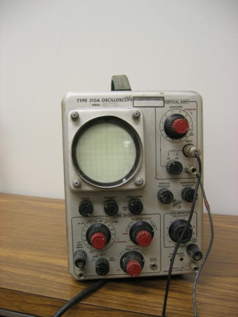
Here is a photo of the cleaned, repaired scope

Here is the photo as provided by the seller:
Here are some images of the 310A as received, opened up, with knobs removed for cleaning etc..


Restoration/repair
Mechanical/cosmetic: I looked carefully over the scope, took all the knobs and binding posts off, cleaned them, re-seated all the tubes, lightly oiled the case hinge, cleaned the panels including the front panel. I removed the graticule and housing, cleaned them and also removed the graticule bulbs and checked them. I now need to replace all the knobs etc. and apply power and make electrical tests. From a mechanical point of view I noted the following problems:
- One binding post (bottom right hand corner) broken ... half the post is missing
- Five of eight feet present, only two of those feet have the rubber cushion inserts
- Graticule badly scratched in two places
- There are two rubber washers that sit between the graticule and the metal cover ... different sizes. Not sure if there should be four (one for each post)
- One of the two graticule bulbs is DOA
I removed and cleaned all the knobs and binding posts in warm soapy water, and dried them thoroughly. I cleaned the front and side panels using a thin solution of grease-cutting detergent. I sprayed all the shafts of the controls sparingly with silicon based contact cleaner.
Larry Christopher kindly sent me a replacement graticule and a few other parts (including a replacement bulb for the graticule lighting).
Electrical: I started out by checking the voltage supplies: all except the very high voltage which my DMM wont go up to, and which I am nervous about getting near anyway. The lower voltages all checked out well. (I tweaked the -150V pot to bring it up from -146, the 100V and 300V were both within a Volt after this tweak).
Then I looked at the Calibrator, which has a simple circuit. The voltages looked OK, as per the manual, within a Volt or so, except around V501B where they were way off. I twiddled the Cal. Adj. R510 and everything started working: the circuit voltages were correct after I adjusted R150 for 20V on the plate of V520. I think it was originally hard over in one or the other direction. I looked at the Calibrator output on my 556 and it was nice and clean. So that was a success :-)
I had noticed how the horizontal width of the trace looked like it was stretched out. That was because I had the Horizontal Display set to X5 due to repositioning the knob incorrectly when it was replaced after cleaning.
The current situation is that things seem to work. However, the triggering or something is still not quite right. The leading and falling edges of the square wave from the Calibrator look fuzzy.
My naive guess is that there is some noisy component, a capacitor maybe, fuzzing up the response.
Subsequently I removed every tube in the 'scope in turn, squirted contact cleaner in each socket, and replaced the tube. This improved the situation somewhat, but didn't cure it.
I tried swapping the two 6CL6 tubes in the vertical amplifier for two NOS, but this did not affect the jitter either. I tried swapping around 6DJ8s in the vertical and horizontal amplifiers, but this didn't help either.
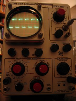
I took a couple of short AVI movies of the jitter, in order to better document what it looked like:
(Triangle wave at 1kHz)
(Square wave at 1kHz)
The problem turned out to be caused by a bad variable capacitor in the vertical amplifier: C205. Once this was replaced, all the jitter problems went away. (Thanks to Stan Griffiths for sending me a replacement part!)
The manual for the 310A is here.
My main Tektronix page is here.